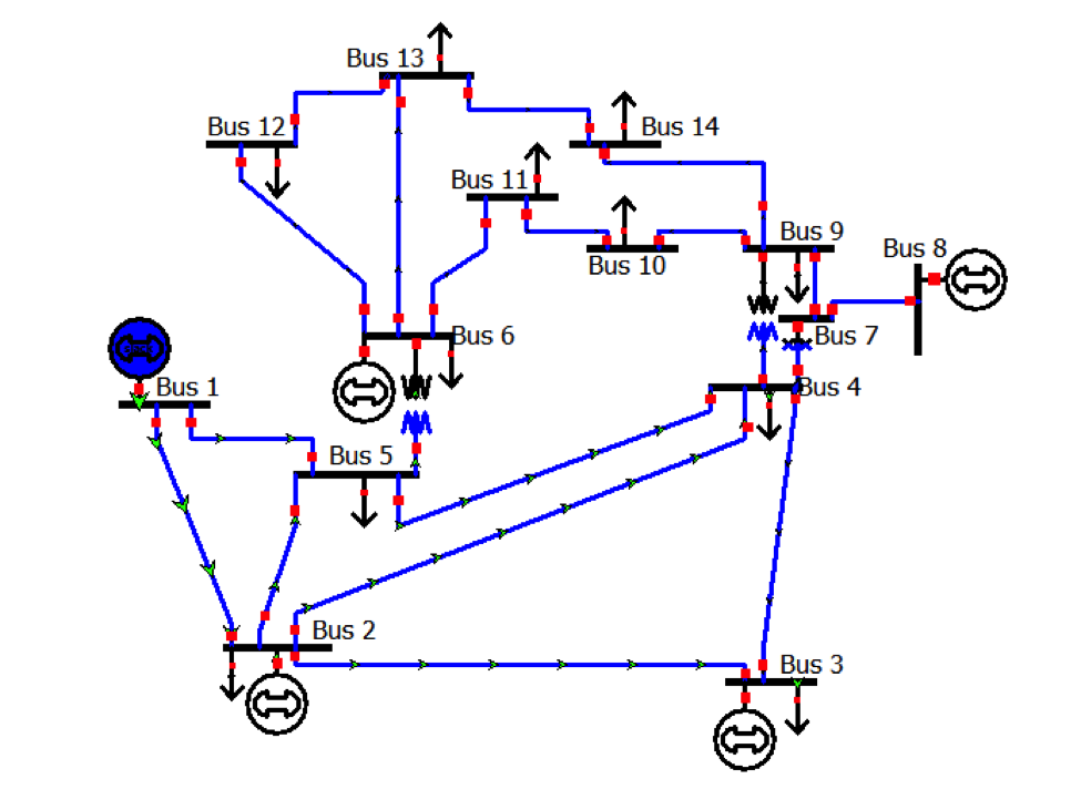
123-bus Feeder: The IEEE 123 node test feeder operates at a nominal voltage of 4.16 kV. This circuit configuration is fairly uncommon. It is characterized by delta configured, all line segments are underground, substation voltage regulation is two single-phase open-delta regulators, spot loads, and very unbalanced. 37-bus Feeder: This feeder is an actual feeder in California, with a 4.8 kV operating voltage. 17 Sept 2010: Error regarding branch 858-864 corrected. It is characterized by long and lightly loaded, two in-line regulators, an in-line transformer for short 4.16 kV section, unbalanced loading, and shunt capacitors. 34-bus Feeder: This feeder is an actual feeder located in Arizona, with a nominal voltage of 24.9 kV. It is characterized by being short, relatively highly loaded, a single voltage regulator at the substation, overhead and underground lines, shunt capacitors, an in-line transformer, and unbalanced loading. 
13-bus Feeder: This circuit model is very small and used to test common features of distribution analysis software, operating at 4.16 kV.Each of these represent reduced-order models of an actual distribution circuit.

These systems were designed to evaluate and benchmark algorithms in solving unbalanced three-phase radial systems. These systems were originally created in 1992 and approved by the DSA Subcommittee during the 2000 PES Summer Meeting.
04 Sept 2012: Wye-Delta Center Tapped Xfm Test Feeder.doc,, Neutral conductor resistance changed from 0.492 to 0.592 Ohms/mile. A good match would have an error less than 0.05%. Since the problems are so small, very close agreement with the test feeder results is expected. Power world simulator feeder network full#
4-Bus Test Feeder Cases: These test the capability of a program to represent transformers of various configurations, full three phase lines, and unbalanced loads. The zipped data files require Microsoft Word and Microsoft Excel to read them. The original test feeder paper and data are provided below. McDermott, and W Kersting, “Analytic Considerations and Design Basis for the IEEE Distribution Test Feeders,” IEEE Transactions on Power Systems, vol. PW 2.33 PW 2.NEWS: New journal article published summarizing working group efforts and intended uses of Test Feeders. What single value of Qcap would minimize the average losses? Assume that can can only be varied in 0.5 Mvar steps. For the system from Problem 2.32, assume that half the time the load is 10 MW/5 Mvar, and for the other half it is 20 MW/10 Mvar. What value of Ocup minimizes the real power line losses? What value of Qcap minimizes the MVA power flow into the feeder? FIGURE 2.28 Source Voltage = 14.98 kv Screen for Problem 2.32 Feeder Impedance = 1 + j2 Ohms | Power into Feeder at Source 8.42 M 4.84 Mvar 9.71 MVA 13.80 kV Feeder Losses = 0.420 MW 0.840 Mvar 8.0M 4.0 Mvar 0.0 Mvar For the system from Problem 2.32, plot the real and reactive line losses as Qcap is var- ied between 0 and 10.0 Mvars. 
The load is compensated with a capacitor whose output, Qap, can be varied in 0.5 Mvar steps between 0 and 10.0 Mvars. In PowerWorld Simulator Problem 2.32 (see Figure 2.28) a 8 MW/4 Mvar load is supplied at 13.8 kV through a feeder with an impedance of 1+2 2.


 0 kommentar(er)
